Why is heat dissipation critical for high-power LED sports lights? The answer begins with a simple physical fact: every watt that does not become visible light becomes heat. In a stadium, that heat remains trapped inside compact luminaires, often above the playing field and under long operating cycles.
The U.S. Department of Energy’s LED Luminaire Lifetime report identifies junction temperature as a major factor affecting lumen maintenance and component reliability. Its testing guidance, including LM-80 and TM-21 methods, shows why thermal performance must be measured rather than assumed. The Illuminating Engineering Society also emphasizes temperature control when evaluating LED lifetime, color stability, and driver performance. These findings matter during real matches. A poorly cooled fixture can develop hotter circuit boards, weaker output, color shifts, and earlier driver failure. Not dramatic at first. Expensive later.
Roland Haitz, a respected LED industry pioneer, stated, “The LED is a semiconductor device, not a light bulb.” That distinction shapes every serious sports-lighting design. High-power LEDs need airflow, conductive materials, correctly sized heat sinks, and verified thermal interfaces. Field experience adds another warning: a fixture may feel acceptable outside while its internal junction temperature remains excessive. That assumption deserves scrutiny.
This article presents the top ten reasons heat dissipation matters for sports LEDs. It connects thermal design with brightness, energy use, maintenance access, broadcast quality, and player visibility. The U.S. DOE Solid-State Lighting reports provide technical context, while LM-80 and TM-21 offer recognized evaluation methods. Better cooling is not merely an engineering preference. It protects performance when the stadium lights cannot afford a failure.
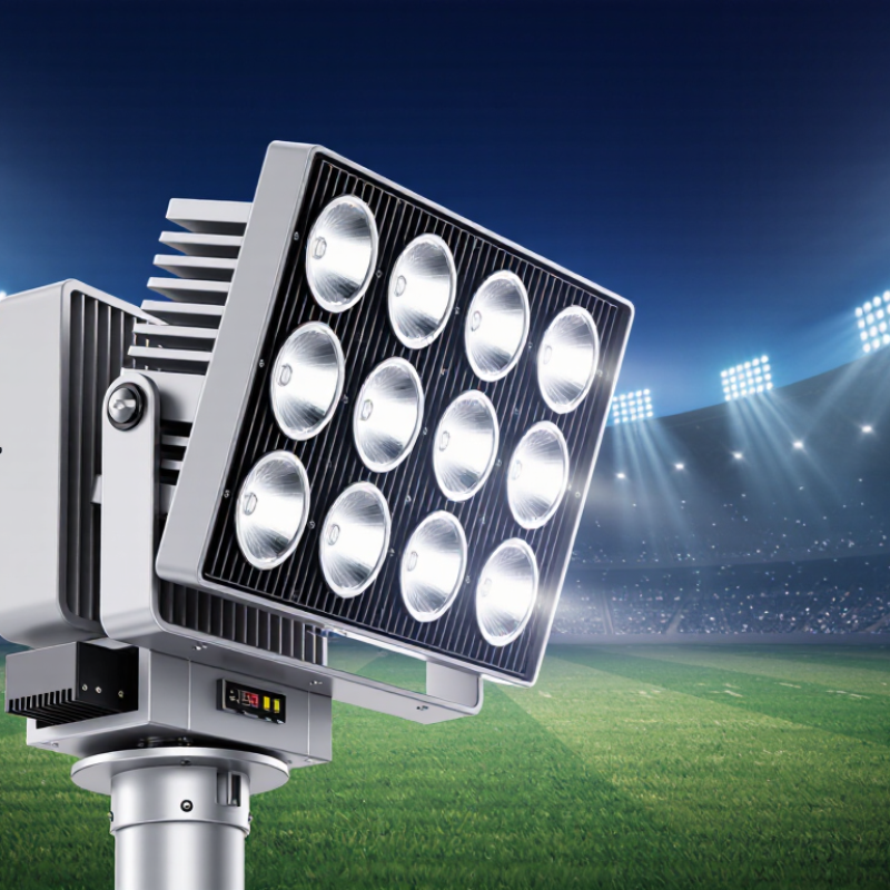
In sports LED lighting, heat does not disappear after electricity enters the fixture. Most input power becomes heat around the LED junction and driver. That heat travels through solder layers, a circuit board, thermal material, and a metal heat sink. Fins then release energy to surrounding air. Air movement matters. A closed housing can trap warm air, especially beneath stadium roofs or dusty canopy structures. Outdoor fixtures also face sunlight, humidity, and sudden temperature changes.
Thermal design starts with the junction temperature, not the advertised wattage. Engineers estimate heat load, then verify it with thermocouples or calibrated infrared measurements. Infrared readings can mislead when surface emissivity is ignored. The mounting surface must be flat, clean, and firmly tightened. A thin, even thermal interface layer usually transfers heat better than a thick, uneven one. This detail is easy to overlook. The driver also needs clearance, because its losses add heat inside the enclosure.
When heat remains high, light output can fall, color may shift, and component life can shorten. In a sports venue, that may create uneven brightness across a playing surface. Good systems therefore combine suitable heat sinks, open airflow paths, protected vents, and temperature monitoring. Maintenance crews should remove dust and check fasteners during scheduled inspections. I have seen clean lenses paired with blocked cooling fins; the fixture looked cared for, but thermal performance suffered. No design is perfect. Ambient conditions, installation errors, and aging materials still require review.
A stadium LED can look brilliant during a cool bench test. Under a packed summer fixture, the result changes. The U.S. Department of Energy’s 2022 Solid-State Lighting R&D Opportunities report identifies thermal management as a major reliability challenge. Higher junction temperatures reduce efficacy and accelerate lumen depreciation. Heat travels through solder, the circuit board, interface material, and heatsink. One weak layer increases thermal resistance. Brightness then falls.
Color accuracy can drift too. Excess heat may shift chromaticity, making white light appear slightly green or warm across the field. The IES LM-80 standard evaluates lumen and color maintenance through controlled testing. It commonly requires at least 6,000 hours of measurements. TM-21 then projects long-term maintenance from that data. Those projections help, but they are not a promise for every dusty stadium.
A practical inspection records ambient temperature, case temperature, drive current, and chromaticity coordinates. A thermal camera can reveal blocked vents or uneven heatsink contact before failure becomes visible. Keep airflow paths clean. Check them after construction work. That step is often missed.
A 10°C temperature rise does not produce one universal lifespan penalty. Design, current, optics, and materials all matter. That is the uncomfortable part. Thermal control is measurable, yet field conditions remain imperfect. DOE and IES data should guide decisions, not replace site testing.
| No. | Reason | Thermal Mechanism | Measurable Effect | Indicative Engineering Data | Recommended Thermal Control | Sports-Lighting Benefit |
|---|---|---|---|---|---|---|
| 1 | Preserves luminous output | Higher LED junction temperature increases internal carrier losses and reduces light-generation efficiency. | Light output decreases as junction temperature rises; the reduction is commonly expressed as a temperature-dependent relative luminous-flux factor in LED datasheets. | Typical design objective: keep the LED junction temperature below the luminaire’s rated maximum and preferably below approximately 85 °C for sustained operation. | Use a correctly sized heat sink, low-resistance thermal interface material, adequate airflow, and temperature-aware drive current. | Maintains more consistent illuminance on the playing surface and reduces dim-looking areas during long matches. |
| 2 | Extends LED service life | Heat accelerates lumen depreciation, solder fatigue, phosphor aging, and degradation of encapsulation materials. | Rated life is normally reported as an L70 or L80 projection, meaning the time until light output reaches 70% or 80% of its initial value under defined conditions. | Life reporting: L70 and L80 are maintenance metrics, not guarantees; actual life depends on temperature, current, duty cycle, and environmental conditions. | Reduce thermal resistance from LED junction to ambient and validate the complete luminaire with temperature and lifetime testing. | Reduces relamping interruptions, access equipment, and maintenance work around spectator and athlete areas. |
| 3 | Protects color accuracy | Temperature changes the spectral output of the LED and can alter phosphor-converted white-light behavior. | Correlated color temperature and chromaticity may shift during warm-up or high-load operation; the visible shift depends on LED construction and optical design. | Useful verification: measure chromaticity and color metrics after thermal stabilization, not only immediately after switch-on. | Control junction temperature, use thermally balanced LED boards, and verify color consistency at the intended operating temperature. | Supports consistent broadcast images, natural-looking uniforms, and stable visual judgment for athletes and officials. |
| 4 | Maintains color uniformity across fixtures | Different fixture temperatures produce different spectral conditions even when the same nominal LED type is used. | Fixture-to-fixture chromaticity variation can increase when thermal paths, mounting positions, or airflow conditions are inconsistent. | Engineering check: compare measured chromaticity coordinates across fixtures after the same operating period and load. | Standardize heat-sink design, thermal interface thickness, LED-board mounting pressure, and enclosure airflow. | Helps prevent visibly different white tones across the field, stands, running tracks, or camera views. |
| 5 | Improves electrical efficiency | As temperature rises, optical efficiency can fall while electrical input continues to generate heat, increasing the share of power lost as thermal energy. | Lower thermal resistance generally improves the relationship between electrical input and usable lumens, subject to the LED and driver design. | Core calculation: Tj = Tc + PLED × RθJC, where temperature rise equals dissipated power multiplied by thermal resistance. | Minimize thermal resistance from junction to case and case to ambient; avoid unnecessary drive-current increases used to compensate for thermal light loss. | Reduces energy consumption for a required illuminance level and can lower operating costs for large venues. |
| 6 | Prevents thermal throttling and unexpected dimming | Many LED drivers reduce output current or shut down protection circuits when temperature limits are approached. | Illuminance may fall suddenly or cycle during hot weather, enclosed operation, blocked ventilation, or continuous full-power use. | Protection principle: thermal foldback should occur only above the intended continuous operating range, with adequate design margin below the protection threshold. | Include temperature sensors, driver thermal protection, airflow analysis, and commissioning tests at maximum ambient temperature. | Protects scheduled matches and broadcasts from sudden brightness changes or incomplete lighting coverage. |
| 7 | Improves driver and power-electronics reliability | Driver components such as electrolytic capacitors, semiconductors, and solder joints are sensitive to temperature and thermal cycling. | Repeated heating and cooling can accelerate material fatigue and increase the probability of driver failure or output instability. | Reliability rule: component life is application-specific; lower operating temperature generally increases reliability, while thermal cycling adds mechanical stress. | Separate heat sources where practical, provide thermal paths for power components, and keep capacitors within their specified temperature limits. | Reduces outages, flicker-related complaints, and emergency maintenance during high-profile sporting events. |
| 8 | Reduces solder-joint and interconnect fatigue | LED boards, connectors, and solder joints expand and contract as fixture temperature changes. | Thermal cycling can create mechanical stress, microcracks, intermittent connections, and eventual open-circuit failures. | Key factors: temperature swing, coefficient-of-thermal-expansion mismatch, board geometry, solder design, and the number of operating cycles. | Use appropriate board materials, compliant interconnects, controlled assembly processes, and thermal-cycle validation. | Improves long-term fixture stability in venues with frequent on/off schedules and large day-night temperature changes. |
| 9 | Preserves optical and sealing materials | Excessive heat can accelerate yellowing, warping, seal aging, adhesive degradation, and changes in lens or reflector performance. | Optical transmission and beam distribution may change, reducing useful light or creating nonuniformity on the field. | Validation requirement: evaluate lens, gasket, adhesive, and enclosure materials at the actual combined temperature, humidity, UV, and vibration exposure. | Keep optical components within their rated temperature range and provide thermal isolation between high-temperature components and sensitive materials. | Maintains beam control, glare management, weather resistance, and consistent coverage for athletes and spectators. |
| 10 | Maintains stable high-speed-camera performance | Thermal drift can change light output, color, and sometimes driver operating behavior during prolonged high-load operation. | Changes in brightness or spectral content may affect camera exposure, white balance, slow-motion replay, and perceived motion quality. | Practical test: record illuminance, chromaticity, and temporal light behavior before and after thermal stabilization at the maximum intended load. | Combine thermal design with driver validation and lighting measurements under realistic broadcast operating conditions. | Supports stable exposure, repeatable color grading, and reliable slow-motion footage throughout the event. |
| Data note: The values and engineering relationships above are general industry reference points rather than product guarantees. Final limits should be taken from the selected LED, driver, thermal interface, optical materials, and complete-luminaire test data. Junction temperature is commonly estimated using the thermal-resistance relationship Tj = Tc + P × RθJC; lifetime claims should be interpreted using the applicable LM-80, TM-21, LM-84, or equivalent test and projection method. | ||||||
Heat dissipation is central to LED lifespan and sports lighting reliability. Sports LEDs often operate for several hours under demanding conditions. Heat trapped inside the fixture raises the LED junction temperature. Excessive heat can reduce brightness, shift color, and accelerate component aging. It can also stress drivers, seals, solder joints, and circuit boards.
Field technicians usually inspect airflow, mounting surfaces, and temperature readings during extended operation. A fixture may feel only warm outside while its internal junction temperature remains dangerously high. Thermal testing with sensors after two hours of operation provides more dependable evidence than a short laboratory check. A design that looks efficient on paper can still perform poorly in a dusty stadium or enclosed structure.
Tips: Keep cooling fins clean and unobstructed. Use solid mounting surfaces that transfer heat effectively. Check ambient temperature, wind conditions, and fixture spacing. Replace damaged thermal pads promptly. Do not rely only on touch; measured data is safer.
Good thermal design reduces sudden shutdowns and helps maintain consistent lighting during matches, training, and broadcasts. It also lowers maintenance pressure because components do not operate continuously near their thermal limits. Engineers should still question every assumption. Even careful calculations can miss reflected heat from roofs, blocked vents, or unusually hot summer nights. Small oversights matter.
Heat is invisible, but it controls LED performance. The International Energy Agency reports that lighting consumes about 15% of global electricity. Efficient sports lighting therefore needs more than high initial lumens. It needs stable thermal control. The U.S. Department of Energy estimated solid-state lighting could deliver 6.2 quads of cumulative energy savings through 2035. Poor heat management can weaken that advantage.
In a stadium, fixtures may run for hours above a warm playing surface. Dusty housings, blocked vents, and hot roof spaces make cooling harder. Heat raises LED junction temperature and can reduce efficacy, color stability, and service life. A proper design uses heat sinks, airflow paths, thermal sensors, and correctly sized drivers. Measure the junction temperature, not only the outer housing. That detail is often missed.
Safety matters too. Excessive heat can stress connectors, seals, insulation, and mounting components. A loose connection may create flicker or an unexpected shutdown during a night match. IES LM-80 and TM-21 provide recognized methods for evaluating LED lumen maintenance, but field conditions remain imperfect. No thermal model predicts every dusty corner. Regular cleaning, infrared checks, and load testing can expose problems early. The U.S. Department of Energy also identifies thermal management as a key factor in maintaining solid-state lighting performance and reliability.
Sports LED systems must manage heat because brightness, color stability, and service life depend on operating temperature. The U.S. Department of Energy’s 2023 Solid-State Lighting R&D Opportunities report records LED package efficacies above 200 lumens per watt. However, higher efficiency still creates concentrated heat inside compact luminaires. Heat sinks, aluminum housings, thermal interface materials, and airflow paths move this heat away from the LEDs and drivers.
Thermal design should match the venue, not only the laboratory. Roof-mounted fixtures face dust, rain, high summer temperatures, and limited airflow. A blocked vent can raise internal temperature quickly. IES LM-80 and TM-21 methods evaluate lumen maintenance using long-duration LED test data, often beginning with 6,000 hours of measurements. These methods support reliable projections, but field conditions remain less predictable. A cool outer housing does not always prove a cool LED board. That assumption deserves review.
Tips: Inspect vents, seals, and mounting surfaces before each season. Remove dust without damaging fins. Check dimming behavior and driver alarms. Record fixture temperatures during night games. A simple thermal log can reveal problems early. Maintenance teams should also compare measured brightness with commissioning records. Small differences matter. No thermal plan is perfect; missed inspections and unusual weather can still expose weak points. Rechecking the design after one full season is practical, and sometimes necessary.
Heat raises the LED junction temperature. Brightness may fall when heat cannot escape through the board, interface layer, and heatsink. A cool bench test can mislead.
Yes. High temperatures may shift chromaticity, making white light look warmer or slightly green. Differences can appear across the field.
Record ambient temperature, fixture case temperature, and internal readings after extended operation. Two hours of operation gives better evidence than a quick check. Touch alone is unreliable.
It can reveal blocked vents, uneven heatsink contact, or unusually hot areas. Inspect fixtures during operation. A visible hotspot may identify trouble before brightness drops.
Keep cooling fins and airflow paths clean. Check them after construction work. Replace damaged thermal pads and use firm mounting surfaces.
No. Internal junction temperatures may remain high while the housing feels comfortable. This assumption is easy to make, and often wrong.
Long-duration measurements commonly begin with at least 6,000 hours of data. Projection methods can estimate future maintenance. They cannot promise identical results in a dusty stadium.
Note ambient temperature, wind, fixture spacing, drive current, case temperature, and color coordinates. Compare brightness with commissioning records. Small differences deserve attention.
No universal penalty applies. Design, current, optics, materials, airflow, and weather all matter. That uncertainty needs honest review.
Review it before each season and after one full season. Check vents, seals, alarms, dimming, and mounting surfaces. Careful plans still miss unusual heat or reflected roof warmth.
Heat dissipation is a fundamental part of reliable sports LED lighting because high-power fixtures generate substantial heat during operation. Why is heat dissipation critical for high-power LED sports lights? Effective thermal control prevents excessive temperature from reducing brightness, shifting color accuracy, or causing uneven illumination across the playing field. By directing heat away from LED chips and electronic components, a well-designed system helps maintain consistent performance during long matches, training sessions, and outdoor events.
Proper heat management also extends LED lifespan, improves system reliability, and reduces the risk of thermal-related failures. Cooler operation can support better energy efficiency by minimizing performance loss and reducing the need for excessive electrical input. It also improves operational safety by protecting internal components and surrounding structures from excessive heat. Sports LED systems commonly combine heat sinks, airflow channels, thermal materials, intelligent controls, and regular maintenance, such as cleaning ventilation areas and checking connections, to preserve stable performance over time.

Suvlux Light